
General Usage Formulas
Calculating Condensate Loads
When the normal condensate load is unknown it can be approximately determined by calculating with the appropriate formula.
Specialized Applications
Properties of Saturated Steam

Effect of Back Pressure on Steam Trap Capacity (% reduction in cap)
How Fast Should Steam Mains be Warmed Up?
The table shows linear expansion in inches per 100 feet of 24” pipe from 0 – 1000°F. It can be noted that for heating up the pipe to 1000°F an expansion of 9.4” is encountered. Rapid heating of such lines would destroy the system and it is, therefore, important to reduce the expansion and temperature stresses as much as possible. An extremely important factor is the ability of the steam traps to discharge condensate as it is formed in the relatively cool pipe. Water hammer must be avoided since it can rupture the pipe or cause valve failure, particularly at the end of the line. Closed gate valves are most susceptible to damage at the end of the line because they can crack at the seat ring when struck by a slug of water. Proper calculating of the heat losses and condensate loads will avoid the backing-up of condensate, and most of the difficulties will be eliminated; however, it is recommended, if the header must be ready for service on short notice, to heat the header with a steam flow through a bypass or a 3/4”, 1” valve first, and only after the pipe has been heated to a certain minimum temperature of approximately 250°F should high pressure steam be admitted to the line. Velan traps operate from 0 to maximum pressure and can handle this job, however, bypasses are recommended, and here the Velan Piping King can offer great savings. The stressing of pipes under such conditions are enormous, and it is important to provide proper expansion loops and expansion joins to keep the effective stress forces within allowable limits.
Stresses can be calculated from a formula:
of expansion of pipe material (in/∆°F)
TD = The difference between the initial and final temperature of the pipe
Temperature Expansion of Pipes per 100 Feet (inches)
Calculating Condensate Loads
Warm Up Load ( Heating Loss ) This is the amount of condensate which forms at starting up a power plant to raise the temperature of the metal of pipes, fittings, etc. to the operating temperature without including the normal radiation loss. As far as calculating the condensation load during the warming up period the required time is extremely important for sizing steam traps. Less warm up time increases the necessary capacity per trap. Allowing more time for warm up permits the use of smaller traps in smaller quantity.
W x (T-t) x Sp. Heat x 60
Q = —————————————
L x m
Where Q = Quantity of Condensate ( Lbs/hr )
W = Total weight of pipes in LBS
T = Saturation Steam Temp ( °F ) t = initial temp of pipe ( °F ) usually surrounding air temp
m = minutes to heat up system
L = Latent heat of steam ( BTU’s/Hr )
Normal Condensate Load ( Radiation Loss )
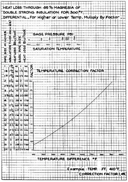
Once the system is heated up steam condenses due to normal radiation losses to the surrounding air. These losses depend of course on the size and length of the pipe, on the pressure of steam and its latent heat and mainly on the type and thickness of insulation. The equation from which a normal regulation load can be calculated is:
F x HL ( T - t )
Q = ——————————
L
Where F = Length of Pipe (ft)
HL ( T – t ) = Heat loss/foot of pipe at the temperature differential between steam and air
L = Latent heat of steam ( BTU’s/Hr. )
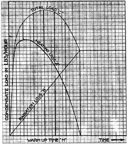
Condensation Load for Sizing Steam Traps
The condensation load builds up from 0 to maximum at the point where the warming up load drops to 0. It is assumed, therefore, that the peak is achieved halfway through the warming up period. Therefore, for sizing of steam traps, we take the maximum amount of condensate during the warming up period plus half of the radiation load.
Qt= QW + .5QR
Where Qt = Total condensation load at peak (LBS/Hr)
QW = Condensation load during warm up (LBS/Hr)
QR = Condensation load due to normal radiation loss (LBS/Hr)
Condensate in LBS/Hr created in steam mains 1” to 24” and pressure of 600 to 2500 PSI based on the warm up period of 1 hour and 100 feet of pipe, and based on the above assumption is shown in tables.
For shorter or longer heating up time, multiply by 60/m where m is the warm up time in minutes.
Properties of Saturated Steam

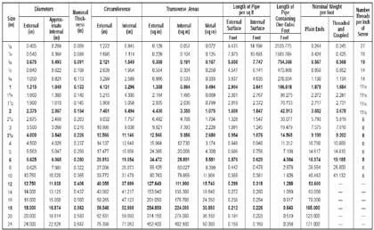
Standard Dimensions for Schedule 40 Pipe
Examples:
Warm up loss
Ambient Temp = 70°F
Working Temp = 366°F (150psig)
Warm up time = 720 minutes
1000 feet of 10 inch Schedule 40 pipe weighs = 40483
Latent heat = 857
40483 x (366-70) x .12 x 60
Q = —————————————
857 x 720
Q = 472 lbs/hr
Radiation loss
Ambient Temp = 70°F
Working Temp = 366°F (150psig)
Differential temp = 294°F
Differential multiplier = .98
1000 feet 10 inch Schedule 40 uninsulated pipe
Latent heat = 857
1000 x 2600 ( .98 [factor for 296° diff] )
Q = ——————————
857
Q = 2973 lbs/hr
Sizing for steam traps
Qt= QW + .5QR
.5QR = 1486.5 + QW = 472 = 1958.5